|
|
|
All About Baluns |
|
 |
ALL ABOUT BALUNS
 What Is A Balun? What Is A Balun?
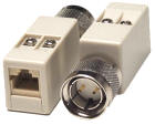
A "balun" is a media adapter with a
built in transformer (as shown at right) connected between a
balanced source or
load and an unbalanced source or load. A balanced
line has two conductors, with equal currents in opposite directions. The
unbalanced line has just one conductor; the current in it returns
through a common ground or earth path.
What Do Twinax Baluns Do?
Baluns are used to convert balanced
signal connections to unbalanced wiring systems to replace expensive
Twinax cable with low cost Category 5 (CAT5) or
Category 6 (CAT6)cables. CAT5/CAT6 cables are commonly referred to
as "Ethernet Cables". They also allow you to connect
workstations to 3X or AS/400 systems in a star-type topology.
Baluns DO NOT convert a Twinax
Signal to a TCP/IP Ethernet Signal. If you need to
connect a Twinax Device to an iSeries AS/400 over an Ethernet TCP/IP
network, you also need to use a "Twinax-Over-IP" controller such as an
I-O Corporation Xip+ Twinax Controller
or a BOSaNOVA eTwinax Controller.
IBM's Twinax cabling connections use a
balanced signal. IBM specifies a Twinax terminating impedance of
about 110 Ohms ? 1%. When you use Twisted Pair wiring, the direct
connections between the devices are lost. Therefore the balun needs to
provide that same impedance. The resistor in the balun provides about 45
ohms. Twinax cable itself provides impedance as well. This combined with
the other components provides the correct impedance.
What Is Important About Choosing &
Connecting Baluns?
Baluns can be either RJ11 or RJ45. These
can not be mixed.
Sometimes baluns are defined using Tip
and Ring terminology following the Universal Service Order Code - USOC
standard. This is a set of codes developed by the Bell System and used
as a standard means of identifying service or equipment. Typically the
lower number connects to the ring. If it is the opposite, it is
sometimes referred to as ?reversed?. This is not the best
terminology to use in reference to Twinax baluns, because there simply
is no standard for which pin inside the Twinax connector is Ring and
which is Tip. Ring and Tip are really Coax cable terms, because that
cable has a single conductor (Tip) in the middle of the cable and a
shield (Ring). Twinax has two conductor pins. They are labeled phase A
and phase B. There will be two signals; one connects to the Twinax phase
A pin, and the other to the phase B pin, but since Twinax has two tips,
and zero rings, you can not truly say that either pin is Tip or Ring. All that you can say is which pins are active, and which pins of the RJ
connector connects to A or B of the Twinax connector. The signals can
not be mixed when using baluns back to back. Some Multiplexers, like the
NLynx Gemini Mux, can not auto-detect polarity, so that it does not
matter.
Usually you use UTP (Unshielded Twisted
Pair - RJ45 CAT5 or CAT6) if STP (Shielded Twisted Pair) cable, it must provide 110 ohms of
impedance. There must be some impedance provided by the wire or an
internal resistor. If the twisted pair wire run is short, you can
use Twinax pigtails.
Requirements:
- Balun pin-out must match at both
ends.
- Never daisy-chain baluns.
- Never use in a series.
- No duplicate
Twinax station
addresses when connected to the same Twinax Host
Port.
Recommendations:
-
Should be used in pairs when
possible.
-
Make certain wire color continuity is
maintained end to end.
-
Make certain tip and ring polarity is
not reversed.
-
Do not use flat (silver satin) cable. Only
CAT5 or CAT6.
-
If using STP, it must have nominal
impedance very close to 100 ohms.
-
Allow a 10-foot service loop at each
end to allow room to move the equipment easily and provide a minimum
length of Twinax cable to provide the expected cable impedance.
-
Not more than 2/3 of the twisted
pairs in a multi-conductor cable should be used for data.
-
For each mechanical connection in a
cable run, reduce the maximum allowed distance by 30 feet (9
meters).
-
Avoid running data transmission wiring near sources of RF or
electromagnetic radiation.
Maintain the
following distances:
-
5 inches (125 mm) from a power line of 2 kVA or
less.
-
12 inches (305 mm) from fluorescent lighting and
power
-
36 inches (915 mm) from power lines more than 5 kVA.
-
40 inches (1015 mm) from transformers and motors
Wire specifications:
|
Wire Size
|
AWG No. 24
or larger
|
|
Type
|
Solid
copper, twisted pair wire with at least two twists per foot (six
per meter)
|
|
Insulation
|
PVC (good)
or Teflon (best)
|
|
dc
Resistance, maximum
|
28.8 ohms
per 1000 feet
(93.8 ohms per 1000 meter)
|
|
Impedance
|
90 to 120
ohms at 256 kHz
87 to 117.5 ohms at 512 kHz
85 to 114 ohms at 772 kHz
84 to 113 ohms at 1000 kHz
|
|
Attenuation,
maximum per 1000 feet (305 m)
|
4.00 dB at
256 kHz
5.66 dB at 512 kHz
6.73 dB at 772 kHz
8.20 dB at 1000 kHz
|
|
Industry
Specifications (meet one)
|
ANSI/ICEA
S-80-576-1983
REA PE-1
Bell System AT&T 48007
|
Recommended Maximum Transmission Distances:
|
WIRE GAUGE
|
DC
Resistance
Ohms/100 ft
(ohms/100 m)
|
Ideal EMI
environment
ft (m)
|
Average EMI
environment
ft (m)
|
Poor EMI
environment
ft (m)
|
|
19
|
2.1 (6.9)
|
2050 (625)
|
1640 (500)
|
1230 (3750)
|
|
22
|
3.3 (10.8)
|
2000 (610)
|
1600 (490)
|
1200 (365)
|
|
24
|
5.2 (17.1)
|
1575 (480)
|
1260 (385)
|
945 (290)
|
|
26
|
8.3 (27.2)
|
1050 (320)
|
840 (255)
|
630 (190)
|
How Do I Know What My Environment Is?
Ideal EMI Environment applies where EMI is minimal.
Average EMI Environment applies to
buildings having large quantities of computer cables routed throughout
the building and/or coiled cables, wiring closets within the computer
room and fluorescent lighting ballasts within 5 feet (1.5 m) of the
twisted pair wiring. It includes twenty or more active FCC Class A
devices, such as computers, monitors, heater fans and air
conditioners.
Poor EMI Environment applies to large industrial plants having
electrical transients of 330 to 400 kV, such as are produced by
three-phase motors, welding equipment, auto-insertion equipment, air
compressors, industrial ovens, large numbers of electrical motors,
and combustion engines.
What Do I Need To Know About Types of "RJ"
Connectors?
-
RJ11
- Short for Registered Jack-11, a four- or six-wire connector used
primarily to connect telephone equipment in the United States.
RJ-11 connectors are also used to connect some types of
local-area networks (LANs), although RJ-45 connectors are more
common.
-
RJ12
- (a.k.a. 6-wire RJ11) modular phone connectors are used for all RS-232
communications. This has several advantages, including:
All jacks have the same polarity, simplifying
interconnection
Routing can be easily changed using simple,
compact distribution panels
Signals may easily be tapped, for
troubleshooting
-
RJ45
- Short for Registered Jack-45, an eight-wire connector used commonly to
connect computers onto a local-area networks (LAN), especially Ethernet.
RJ-45 connectors look similar to the widespread RJ-11 connectors
used for connecting telephone equipment, but they are somewhat
wider.
Potential Problems:
-
RJ11 can be four or six wire. And because six pin is more common than
four pin, when the specifications state "pins 3&4 active of RJ11
versions", what is meant is 'the middle two pins'. The middle two
pins for a six-wire connector are 3&4. But if you only had a 4-pin
connector, then you would get 2 & 3.
-
Star products sometimes allow you to jumper select either
the middle two, (referred to as 3 & 4, assuming a six pin
connector) or the next two outside (which would be 2 & 5).
|